Advertising:
Siemens MS42
The Siemens MS42 engine control unit (ECU) uses an Infineon C167CR_SR CPU clocked at 20MHz in combination with a 4 megabit AMD AM29F400BB flash memory. This ECU controls the BMW M52TU inline six engine.
When looking at the cryptic item names this might help you: Siemens Keyword Translation
Memory Layout
The MS42 can be seperated into three major sections, the bootloader, the program code, and the calibration data.
See this table for file locations:
| Start | End | Section | Size |
|---|---|---|---|
| 00000 | 0FFFF | Bootloader & UIF | 64 kByte |
| 10000 | 1FFFF | Program Code 1 | 192 kByte |
| 20000 | 2FFFF | ||
| 30000 | 3FFFF | ||
| 40000 | 47FFF | Unused Space | 32 kByte |
| 48000 | 4FFFF | Calibration Data | 32 kByte |
| 50000 | 5FFFF | Program Code 2 | 192 kByte |
| 60000 | 6FFFF | ||
| 70000 | 7FFFF |
Bootloader Section
The bootloader code section is the most important section of the MS42 and doesnt have to be touched for at least 99% of all use cases.
This section is 64 kByte in size and contains the interrupt setups, input and output initializations, as well as immobilizer information and the UIF (user information fields).
The significant difference between the bootloader section and the others is, that it's only one time programmable under normal operation. That means once a byte has been changed from FF to another value, it is not changeable again.
Unlimited write access to the bootloader section can only be archieved through JMGarage Flasher and is ONLY needed for virginizing the ECU to pair it with a different EWS module or to alter the UIF without increasing the flashcounter.
Note: The newest version of immobilizer and checksum delete will not need bootmode flashing.
Programm Code Section
The program code section is divided into two 192kByte large sections with the calibration data in between.
Calibration Data Section
The calibration data section is 32kByte in size and contains all constants and tables.
Checksums
The MS42 uses three CRC16 checksums that covers the boot, program and calibration sections. The checksums are used to verify that the data written to the ROM has not become corrupt.
The checksums are located at the following addresses:
| CRC16 | Location |
|---|---|
| Boot | 0x3C24 |
| Program | 0x50306 |
| Calibration | 0x4FEE0 |
Disabling Calibration Checksums
Disable CRC16 Checksum
To disable the CRC16 calibration checksum do the following.
- Hexeditor
- 1. Set Word at 0x4FEFE to 0xFFFF
- 2. Set Byte at 0x5002C to 0xA8
Fueling
Basic Fuel Maps
Injection maps are based around engine load vs engine speed. The lookup is milliseconds. The lambda sensors for closed loop control are narrowband. Learned trims do affect full throttle fuelling as well, but area learned from closed loop areas. When there is no VANOS fault, the engine interpolates between Injection time at part-load, cold engine, Vanos I or II and Injection time at part-load, warm engine, Vanos I or II. I or II are for the two halves of the straight six engine. Under VANOS fault conditions, Basic Injection Time IP_TIB is used. Full load enrichment IP_TI_VL is a multiplier of the part load calculations and added to them. Blending between cold and warm injection maps is done by weighing factor kf_fak_vanos_tl__tkw__tkw_st for partload and kf_fak_vanos_ll__tkw__tkw_st for idlespeed
Non Stock Injector Maps
Changing the fuel injectors may be needed when charging your engine and therefore some constants and maps need to be tweaked.
You will have to calculate the difference in percentage of volume flow between stock and your new injectors.
The following scalars need to be adjusted accordingly:
- T_TI_AS_[0-5]
- ti_min_ev
Depending on the injectors you will have to finetune the injector latency compensation (injector dead times) as well:
- kf_ti_add_totz__ub
But adjusting the scalars will only get you to rough ballpark. The engine will probaply run just fine only with T_TI_AS adjusted but to get fueling dialed in you need to fine tune other fuel maps:
- kf_ti_kst__n__tkw
- kf_ti_tkw1_vanos_ll__n__lm
- kf_ti_tkw2_vanos_ll__n__lm
- kf_ti_tkw2_vanos_tl_bk1__n__lm
- kf_ti_tkw2_vanos_tl_bk2__n__lm
- kf_tib__n__lm
- kf_vti_kst__tkw
If you happen to have stuttering or unclean combustion when stepping on the gas, rescale the cylinder rewetting tables as well:
- kf_ti_swf_min__tkw
- kf_ti_lwf_min__tkw
Timing
Basic Timing Maps
Ignition at part-load, RON98 (16x20) Airflow -vs- Engine speed (kf_zw_roz98_vanos_tl__n__lm) is the main table in use with a healthy engine, with no VANOS fault codes at normal warmed up operating temperature running 98 RON/93 PON gasoline. There is a knock based interpolation between the 98 and 91 RON tables. The other tables should be kept safe. Ignition at part-load, cold engine (16x20) Airflow -vs- Engine speed is used on a cold engine, and blended/interpolated towards Ignition at part-load, RON98 (16x20) Airflow -vs- Engine speed during warm up. Catalyst heating "KH" in maps retards ignition during warm up. Antijerk "AR" retards ignition during rapid throttle opening to smooth out torque (can be removed by increasing tkw_min_ar to 142.5C. Reported to sometimes cause transitional knock on boosted engines, if so consider adjusting other tables designed for this (***). MS43 related: Experience on standard or near standard Euro 330ci in cool climate and with 99 RON fuel suggested sporadic pulling of timing here and there up to a few degrees is common but rarely sufficient even in hard track use to produce more than 1 degree of learned ignition retard from the 98 RON base map. Shows the 98 RON map on a standard car is quite good. Question if fuelling could be richened to allow more ignition timing and torque/power.
Exhaust Popping Modifications
Current solution for exhaust crackle/pop is to supress overrun fuelcut detection from the ecu. This is accomplished by raising the rpm treshold. As this engine state can be set differently when A/C is turned on and off, you can switch between both states by operating the A/C.
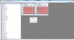
The following maps need to be tweaked. Note: The screenshot actually shows the values to have crackle/pop when A/C is off
Vanos
This section contains information on how the dual vanos system is actuated by the DME and how to modify it. Both, intake and exhaust, camshaft can be set independently in relation to the crankshaft. The aim of that system is to optimize emission, produce better torque at low engine speeds and have better top end power. The system uses engine oil to pressurize a set of gears at the end of each camshaft. Even though the variation of °crk is pretty limited, it can be used to compensate for different intakes, different camshafts and even turbo application may be benefitting from perfectly tweaked camshafts.
Basic Vanos Maps
The main maps used for intake camshaft are:
cold engine
- kf_nwsoll_tkw1_ll_e__n__lm_van(os)
- kf_nwsoll_tkw1_tl_e__n__lm_van(os)
- kf_nwsoll_tkw1_vl_e__n
warm engine
- kf_nwsoll_tkw2_ll_e__n__lm_van(os)
- kf_nwsoll_tkw2_tl_e__n__lm_van(os)
- kf_nwsoll_tkw1_vl_e__n
The main maps used for exhaust camshaft are:
cold engine
- kf_nwsoll_tkw1_ll_a__n__lm_van(os)
- kf_nwsoll_tkw1_tl_a__n__lm_van(os)
- kf_nwsoll_tkw1_vl_a__n
warm engine
- kf_nwsoll_tkw2_ll_a__n__lm_van(os)
- kf_nwsoll_tkw2_tl_a__n__lm_van(os)
- kf_nwsoll_tkw1_vl_a__n
Blending between cold engine and warm engine is done by:
idlespeed kf_nwsoll_fak_ll_e__tkw__tkw_st kf_nwsoll_fak_ll_a__tkw__tkw_st
partload kf_nwsoll_fak_tl_e__tkw__tkw_st kf_nwsoll_fak_tl_a__tkw__tkw_st
DTC Suppression
DTC's can be suppressed in the MS42 by zeroing out the epz_inc_... specific codes. The full list of DTC's can be found here: (NEED SPREADSHEET)
Extra Features
Change E-Thermostat Desired Temp Maps
The M52tu runs quite warm for the aluminum block and also is very sensitive to temperatures and is one of the leading causes for pulling timing when warm. To set the desired coolant temps, the following maps need to be adjusted:
- tkw_soll_toel_min (Minimum Oil temp required to then default to EThermostat maps - default 102°C)
- tab_tkw_soll_kfk__n__lm_ers(Target Coolant temp without AC)
- tab_tkw_soll_kfk_ka__n__lm_ers (Target Coolant temp with AC)
Secondary Air Pump Delete
Disabling Secondary Air Pump from configuration should be enough for SAP delete:
- Set konf_ssp = 0
Alternatively secondary air pump delete can be done how cars without it from factory have been set up:
- Zero out secondary air valve and pump -on maps (tab_t_slv_ein__tkw_st and tab_t_slp_ein__tkw_st)
- Disable DTC's 35, 62 and 50
Post Cat O2 Delete
Set - konf_abgasanlage - Configuration Catalytic System to 1 for 2 Pre-Cat O2 sensors
Single O2 Feedback
Constant konf_abgasanlage has 4 different options which represent the ecu´s ability to work with different lambda probe setups. Set the following values that suit you needs:
- 0: One precat lambda sensor or cat-preparation (SA199)
- 1: Two precat lambda sensor or cat-preparation (SA199)
- 2: One precat lambda sensor and one postcat lambda sensor
- 3: Two precat lambda sensor and two postcat lambda sensor
MAF Scalar Adjustments
The standard MAF lookup table is a 16 * 16 table that is not interpolated. (The table can also be shown as 256 * 1)
The 10 bit analog to digital conversion is reduced to 8 bits and 4 bits of each are used to lookup the MAF.
There is a factory limit of 1024kg/h that can be doubled or quadrupled with a patch that has undergone basic testing.
There are differences in flow between the M52TUB22/25/28,M54B22,B25 and M54B30 MAF sensors.
Differences in cross sectional area would be expected to rescale the values, but the sensor is part of the tube and not easily modified.
BMW sensors apparently not well suited to boost in blow through setup.
Replacement slot type sensors are often used in high output blow through configurations for turbocharging.
For less demanding using the bigger M54B30 MAF sensor is an easy upgrade which will fit directly to stock M52TU wiring. The MAF scalar can be copied from M54B30 MS43 and will work right away.
Alternatively MAF range can be extended using resistor in MAF signal wire. Normally 1k to 2.2k resistor is enough for even boosted application.
Use this excel sheet to calculate new MAF scalar when using resistor on signal wire.
Engine load is proportional to MAF divided by RPM and is used to reference most of the important fuel and ignition tables. The maximum engine load is 1389mg/stroke and can't be changed unless there are massive rewrites in the program code.
An M54B30 pulls about 600mg/stroke in cold conditions with a maximum airflow of about 630kg/h.
Changes to MAF tables should be kept smooth and progressive. Fuel trims plotted against MAF voltage can be used to fine tune the closed loop areas.
Throttle reaction to accelerator pedal
MS42 uses maps "KF_MDK_SOLL_PWG_TKW1" and "KF_MDK_SOLL_PWG_TKW2" (Cold and Warm respectively.)
Rpm limiter
MS42 has 4 gear dependant rpm limiter, where 2 are used for soft limiting and the other 2 are used for hard limiting. Both hard- and softlimiter are gearbox dependant, AT or MT
- "TAB_NMAX_AT__NTV": Softlimiter for AT gearbox
- "TAB_NMAX_MAX_AT__NTV": Hardlimiter for AT gearbox
- "TAB_NMAX_MT__NTV": Softlimiter for MT gearbox
- "TAB_NMAX_MAX_MT__NTV": Hardlimiter for MT gearbox
0110C6 uses maps:
- "TAB_NMAX_MT": Softlimiter for MT
- "TAB_NMAX_MAX_MT": Hardlimiter for MT
Automatic Transmission maps are the same.
Softlimiter works by cutting injectors based on fuelcut pattern, whereas hardlimiter immediately cuts all cylinders
Vmax limiter
The MS42 uses the table "TV_MAX_VL" Set to 255 for no limiter.
Alpha/n
Disconnecting the MAF sensor forces the DME to use the Alpha/n map (KF_LM_DIAG_1) Fault codes will be removed with the next iteration of flash files.
Safety Features
The following information need to be handled with care as you´re able to turn off safety features! This can lead to severe damage and you´re doing so at your own risk!
Misfire Detection
- n_min_lu: minimum engine speed for detection of misfire!
- n_max_lu: maximum engine speed for detection of misfire!
Knock Detection
- tab_zw_dec_kr_1__n: ignition angle reduction based on knock stage1
- tab_zw_dec_kr_2__n: ignition angle reduction based on knock stage2
Injection Adaptation
- n_ti_ad_fak_min: min engine speed to allow adapation of fuel trim, multiplicative
- n_ti_ad_add_max: max engine speed to allow adapation of fuel trim, additive


